A Solderless Printed Circuit Board
The trouble with bread boards is what happens
when one needs to build something else up. Suppose
there is an easy way to hook up a circuit which
is a bit more like a printed circuit board but is
fast and easy. The
lastest method is used here.
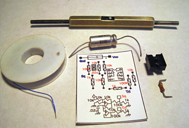
Everything that is needed is shown above. First off, all the
circuit components are required. A manual wire wrap tool is shown
at top with some wire wrap wire shown at the left. Now what if
if a PC board is printed out on paper? This is not a new idea.
A "pPCBs (Paper Printed Circuit Board)" idea has been published
on the web at this site. But it is not obvious that wire
wrap has been discussed.
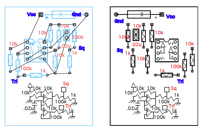
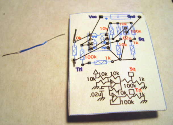
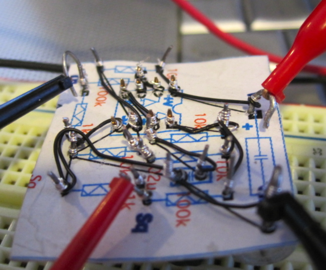
Solder side Component side
Anyone who has done any amount of PCB layout will be familiar with the two
sides of a PCB. A regular PCB layout just printed out on paper could do
the job. The layout shown above however has imported the artwork from
an Open source PCB layout program located at this site.
This application can export data to EPS files which can then be imported to
a vector application where some documentation has been added. The dimensions to
things like dip pinouts and resistor holes will be maintained at the correct
spacings. The solder side on the left is where the circuit gets hooked up.
Having a schematic close by can make the PCB layout a little easier. And labeling
all component sizes is convenient. A vector application can do a flip of
the artwork to generate the component side shown on the right.
This artwork can be found here.
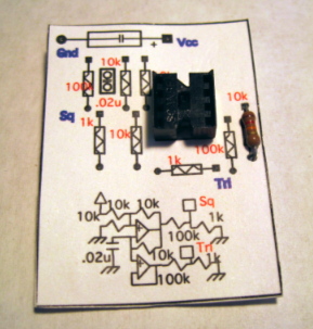
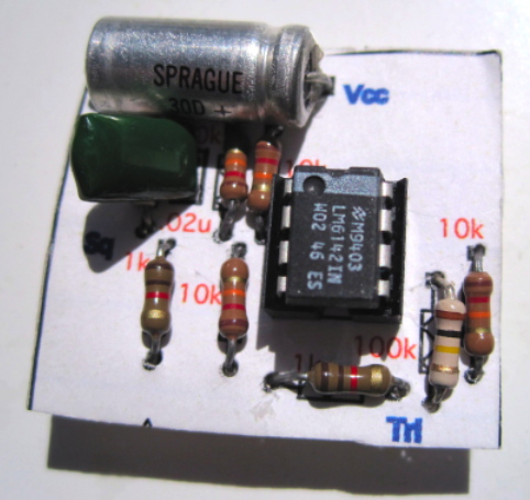
The two sides can be carefully glued to both sides of an index card
such that the holes all line up. Punch holes in the component side, and
the leads of an inserted component will come out through the holes
on the solder side.
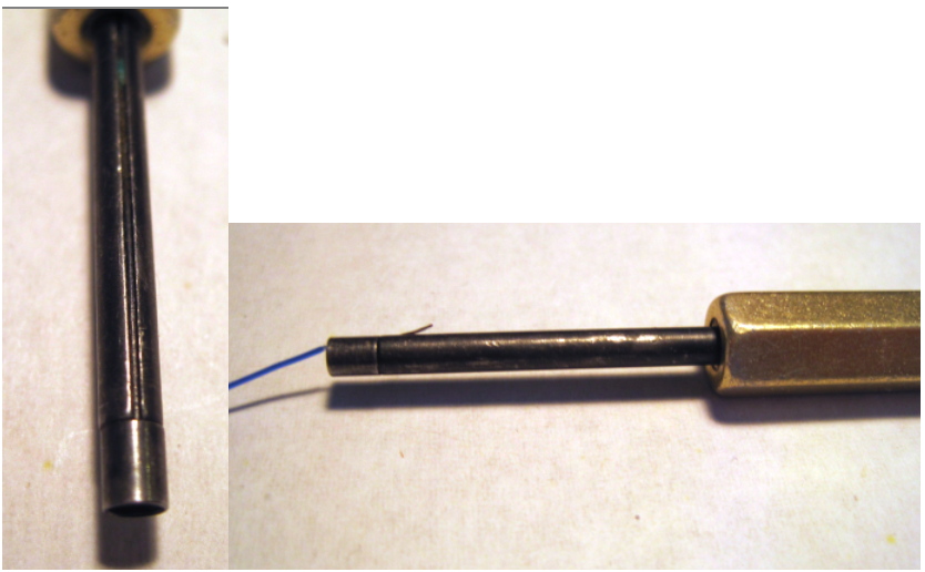
The manual wire wrap tool has a insulation stripper which can double
as a lead length measure. When the unstripped wire is inserted till
it just about comes out the other end, it will be stripped to the
optimum length.
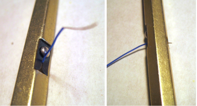
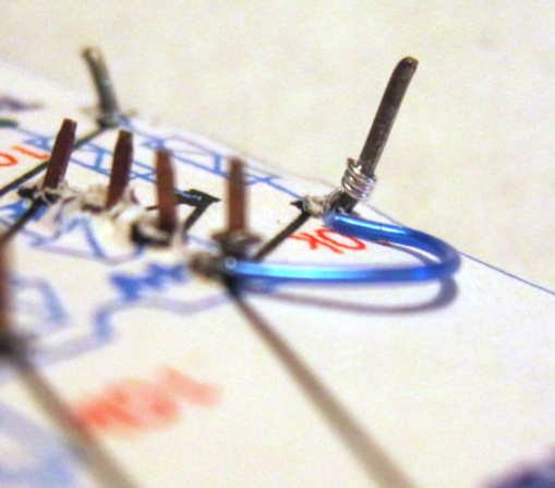
The stripped end of the wire then gets inserted into the groove of the
wire wrap tool.
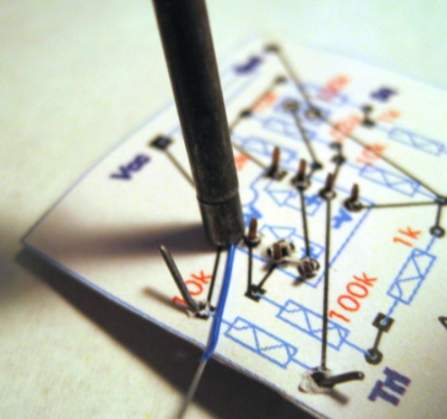
Place the tool over a lead on the solder side and twist until all the bare wire
is wrapped around the lead.
Wire wrap is not as solid as soldering, but it comes close.
If the stripped wire is at the optimum length, several
wraps can be made on every pin. And the bare wire can
be counted on to make contact.
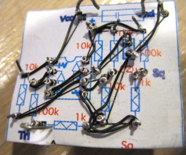
Wire wrap can make a lot of different connections in close
quarters. Documenting component values and where wires go
makes it much easier to hook up everything without
making a mistake.
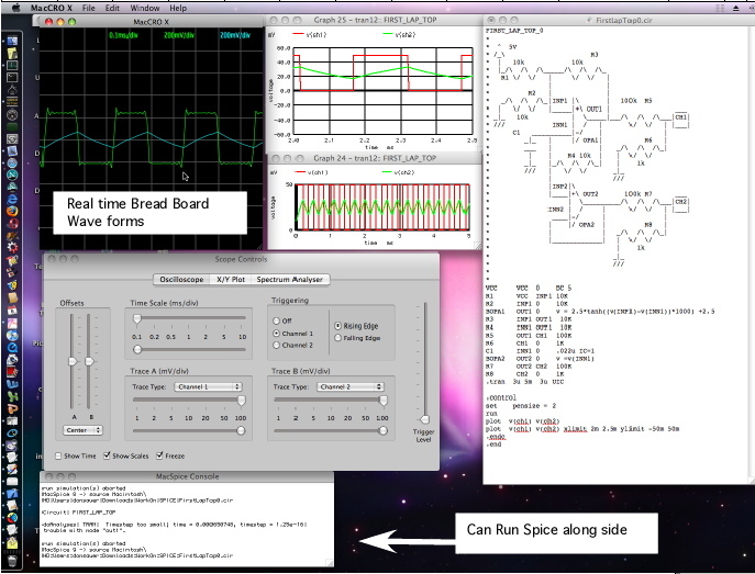
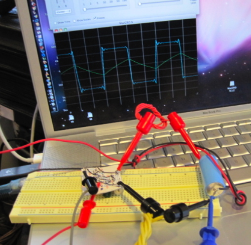
This circuit was designed to operate completely off a laptop
using the standard ports. One can use the laptop as an
oscilloscope while running spice simulations at the same
time.
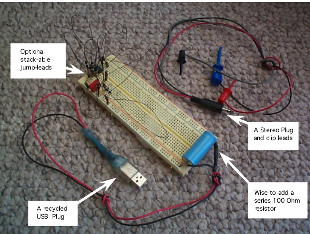
The USB port can supply 5volts at 200mAs, and the audio input
port can AC couple in stereo signal at standard audio levels.
Having the circuit work without any debugging is always nice.
With just wire wrap, the circuit is semi-permanent. This
particular layout might get enough use to encourage adding a
little solder to all the leads. As it stands right now, all
the wires can be removed, and all the components can be
reused.
It may be best to avoid trimming component leads in favor
of looping them. Loops make good scope connections.