*=============BiCMOS_LapTop_CurveTracer=====================
Do it with RRIO quad and a binary counter.
The Arduino
version can be found here.
Cross checking simulations with silicon can save a lot of time and trouble.
Now both of this can be done on the same laptop at the same time.
*=============Making_A_CurveTracer=========================
What does it take to do a curve tracer function in spice?
First a sweeping voltage which is applied to a transistor's collector.
And a staircase current needs to be applied to the base.
In spice this is done with a dc sweep card.
And X/Y plot can be done using the current of VCE vs VCE voltage.
*=============CurveTracer_On_A_LapTop=========================
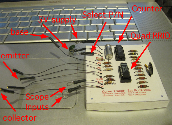
So what does it take to do it all on a laptop?
First off, one needs a power supply.
A 5V supply is available off the USB port.
Second, two scope inputs are needed.
A typical laptop has a stereo input port which can be used for this.
Third, a way to connect at least three wires are needed.
A jumper cable technique previously discussed appears to do the job.
A RRIO Quad Op amp can be used to make a ramp,
but it turns out a triangle wave works better.
A binary counter with some resistors and an op amp makes the staircase.
Rail to Rail opamps can measure signal off either rail.
NPN devices need to read currents going to ground.
PNP devices need to be done off the VCC supply.
This circuit uses a clip lead to select the polarity (PorN) for the DUT.
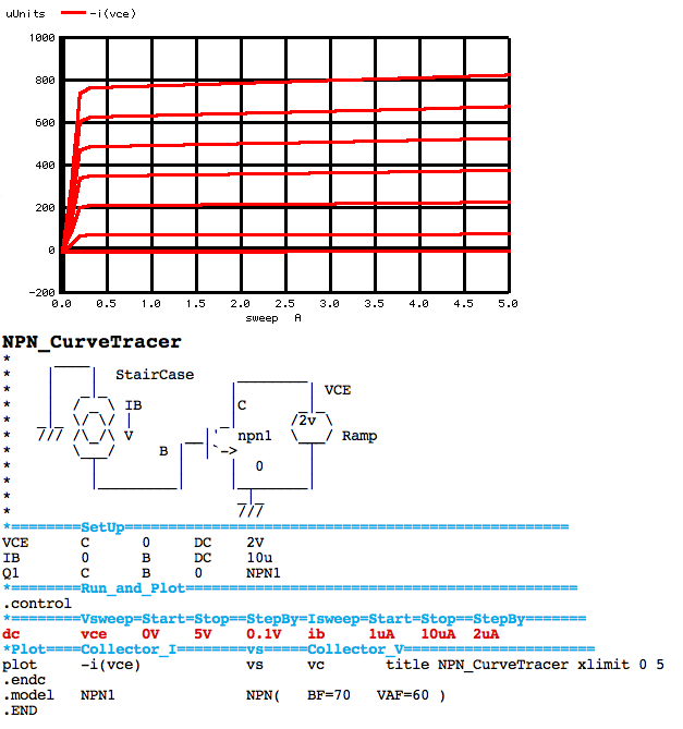
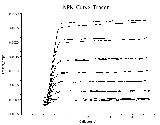
*=============NPN_CurveTracer_Waveform=========================
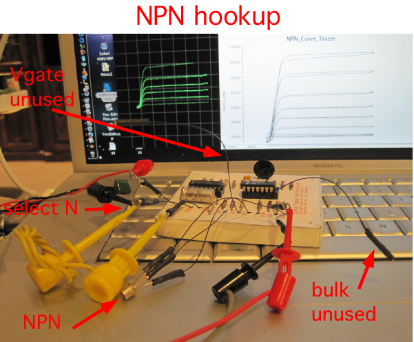
The PorN node needs to be connect to GND for an NPN.
Extra leads (bulk,VG) intended for CMOS devices are being unused.
The TRI(SAW) node is connected to the collector.
The VB Base lead has a 100k resistor in series with the voltage staircase.
The emitter goes to the ICS node.
The two "scope probes" are connected to TRI(SAW) node and ICH.
For a MacBook Pro, a previously discussed a program like MacCRO X.app
can do a X/Y plot to display the waveform.
*=============PNP_CurveTracer_Waveform=========================
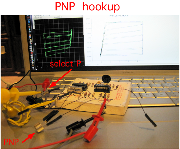
The Emitter, Base, and Collector connections are the same as for an NPN.
But there is a shift in the polarity of currents,
now the emitter current needs to be sensed off the VCC rail.
This is done by connecting the PorN node to VCC.
The waveform will be displayed inverted.
*=============NMOS_CurveTracer_Waveform=========================
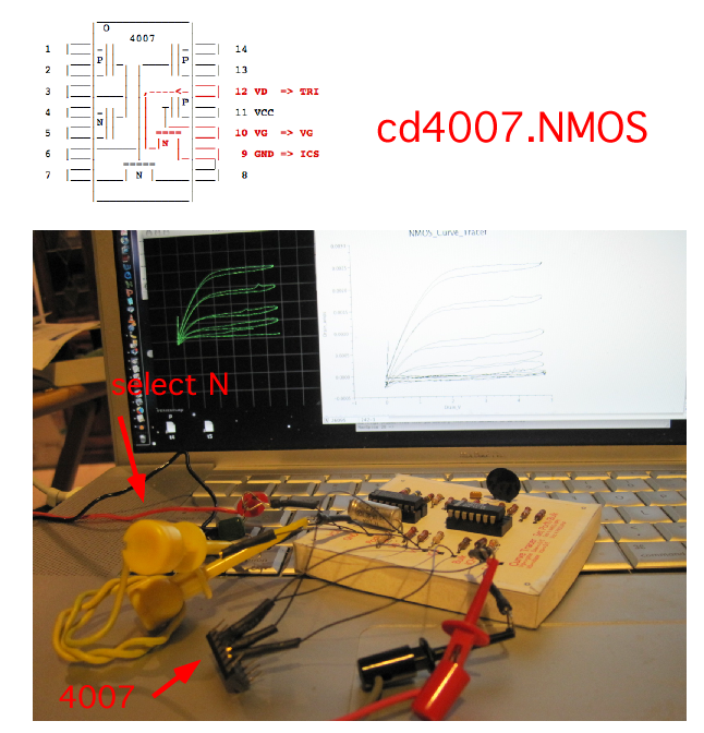
CMOS devices need the VG and Bulk leads.
The Bulk node on a NMOS device needs to be at GND.
For a CD4007 device, this node happens to be pin 9.
The PorN node is connected to the bulk lead.
So connecting the PorN node to GND serves two purposes.
The ICS node gets connected to the source.
The drain gets connected to the TRI (Saw) node.
The VG node connects directly to the Gate.
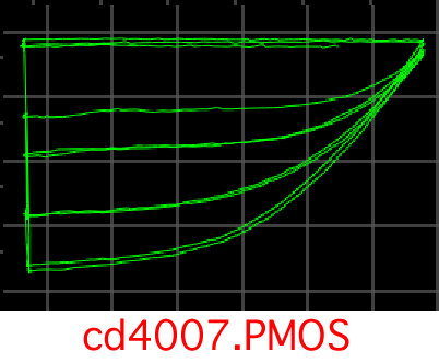
*=============PMOS_CurveTracer_Waveform=========================
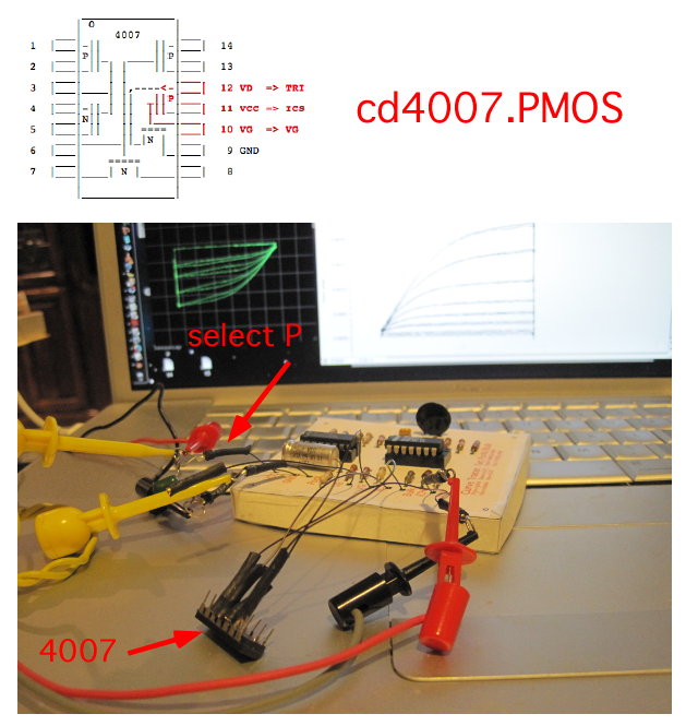
Like Bipolars, Drain, Gate, and Source are the same for both NMOS and PMOS.
But PMOS devices need the bulk attached to VCC.
This is pin 11 in the case of cd4007.
When the PorN node gets connected to VCC,
the bulk lead will be connected to VCC too.
If one happens to use pins 12,11,10, such the pin 11 is at ICS,
then the bulk is already connected inside the IC.
*=============All_the_CurveTraces=====================
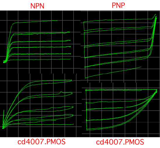
Both polarities of Bipolar and CMOS transistors can be displayed.
So now how does the circuit work?
*=============The_SweepWave_and_StairCase=====================
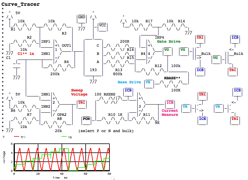
The full MacSpice simulation netlist is included here.
Amplifier_1 is a simple RC oscillator shown in the upper left.
Capacitor C1 sets the speed of the oscillator.
The capacitor C1 voltage gets gained up by amplifier_2.
A clipping rail to rail triangle wave at the TRI port.
This same oscillator is also driving a binary counter.
The outputs of the counter are fed to binary weighted resistors.
Amplifier_4 generates a staircase waveform at the VG node.
*=============The_Current_Measurement=====================
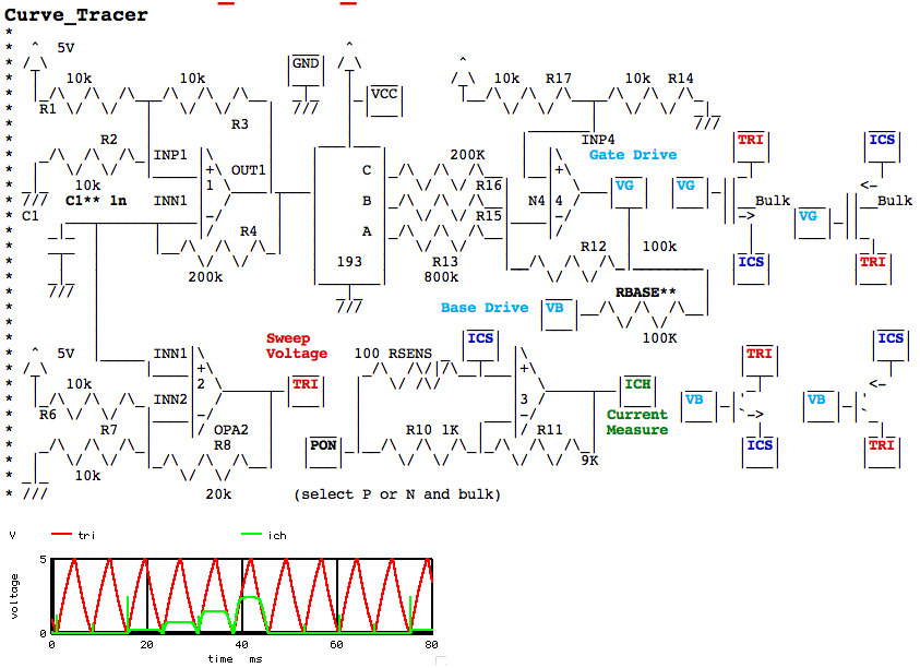
With PorN at GND, the ICS node can measure NPN current going into it.
When connect to VCC, ICS can measure PNP current pulled out of it.
The gain is set for 1mA to generates 1volt shift at the ICH node.
In the simulation, using ramps or sawtooth waves worked.
But using triangle waves appear to work much better in the actual circuit.
The orginal TRI port has been renamed from SAW to TRI.
*=============CurveTracer_Format=====================
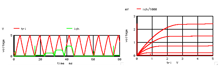
Curve tracer waveforms plot emitter current vs collector voltage.
Do a little gain scaling of current signal,
and then an x/y plot to get the proper curve.
*=============A_Paper_Print_Circuit_Board=====================
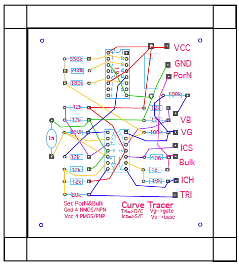
This method uses a paper PC board method together with wirewrap.
The layout for the PC "Board" can be downloaded here.
The schematic has slightly different values.
Different values seem to work better in the circuit.
Capacitor C1 might need to be different for different laptops.
CURVETRACER2.pdf
This method has been discussed earlier as a solderless PC board.
The intention is less to avoid soldering,
and more to make it much easier to solder.
It can cleanly mount several wires to one lead before soldering.
If humans had eight arms, this techinque might not be needed.
*=============No_Hurry_To_Solder=====================
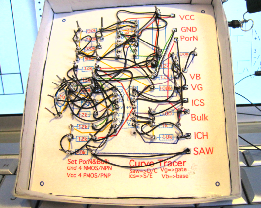
The wire wrap seems to want to mechanically mount the components.
Now all nodes are both mechanically and electrically solid,
and all bare wires are neatly wrapped around a lead.
No hurry to solder,
the circuit will work if hooked up correctly,
and unwrapping wires is easier before soldering.
Some enhancements have been added since the first discussion.
The "board" is now a box.
The circuit can now be used from the component side.
Scotch tape has been added to the sides to reduce wear and tear.
Some previously developed jumper cables have been imported.
They seem to do the job of making connections.
*=============But_So_Much_For_Pretty_Pictures=====================
So what good is just looking at pretty curve tracer pictures.
Curve tracer waveforms need to be in units like volts and amps.
This involves downloading and installing software,
and is discussed in the
handling waveforms section.
The Arduino method of handling
waveforms is a little different.