THE LM6142 STORY
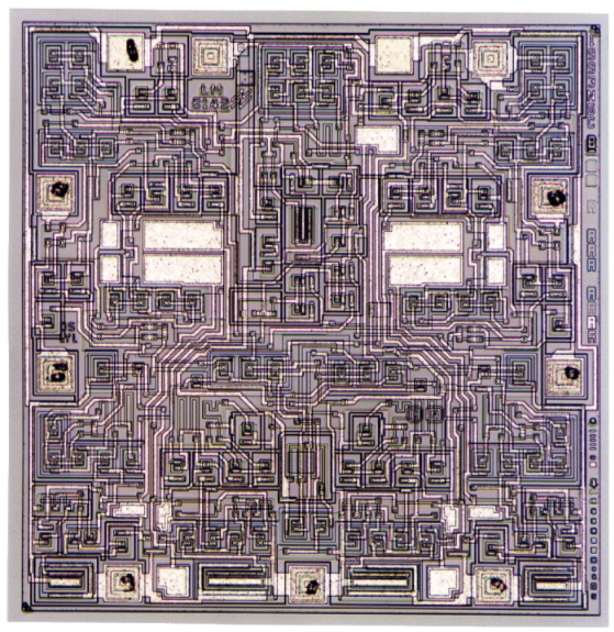
In the early 90s there was a need for a high bandwidth low
supply current Op Amp for cell phone applications. At the
time, National Semiconductor had just developed their second
generation of a "Vertical
Integration Process" which they
called VIP2. In many
ways this was like the standard analog
bipolar process in that it was rated to 30volts. The PNPs
however were now vertical and all transistors were now
several orders of magnitude faster.
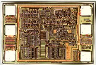
The LM6142 was developed as a result. The die photo is shown
above and the top header for the data sheet is listed below.

At this time, supply voltages were dropping down to 5volts
and customers were buying Rail-to-Rail Input/Output Op Amps
to adjust to the lower supply voltages. The immediate need
was for a dual and quad. The amplifier design department
was having luck laying out a dual Op Amp which could be
doubled up and bonded out as in a standard quad pin out.
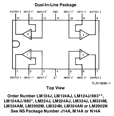
The LM324 has what everyone wanted
with at least ten times
the bandwidth but with around the same supply current.
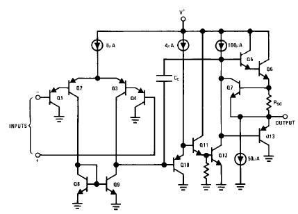
The LM324 schematic which is shown below suggests that
it had taken the first steps towards the RRIO Op Amp. Its inputs
could swing below ground and a collector at the output could
pull the output close to ground.
Rail-to-Rail CMOS Op Amps were being developed and the
requirement that the inputs should be able to exceed
both supplies by 200mV
had become a standard. A bipolar
RRIO needed a dual input stage which could work much
like a LM324.
_______
| |
______________________| |
|
______________| |
_|
|_
| |
__|' NPNs
|___
| |
|
|`-> <-'|
|
| |
| |_______|
|
| |
| _|_ ^ VCC
| |DUAL |
___ | / _
\ /_\
|
| | ___||_______
|INP|___| \/ \/
_|_ | ___ |INPUT
| | || |
|___| | /\_/\ / _
\ |_|INN| |
|
| |
_|__ | \___/ \/
\/ | |___| |TURN |
| |
/_ \ | _|_
/\_/\ | |
| |___|_|\ _ _
| ___
// \ \ | ///
\___/ | | |AROUND
| | \/ \/ \_|_|OUT|
\ \_// |
_______| | |
| | ___| /\_/\_/
|___|
\____/ |
| |
| | |
| |
|/ |
| |
<-
-> | |
| |
|
|
_|_ |_| PNPs
`|_| |
QN| |
_|_
|
///
|`_ _
'| |
| | \ /
VREF |
|
|________/|\__| |
V
|
|
| |
|
|
|__________________/|\_/|
|
|
| |
|
|
|
|_______|
|
|______________________________|
For a Bipolar Rail-to-Rail
Op Amp, at least two input
stages are needed and the supply voltage must be high
enough such that at least one of the input stages is
always on. This implies that the "turn around" which
follows the differential input stage needs to be able
to receive a differential current signal from either
input stage. The requirement of being able to exceed the
rails implies that the "dual
turn around stage" should
be able to receive signal at voltages that are close to the
rails. Biasing the input stages as shown in the circuit
above has some drawbacks.
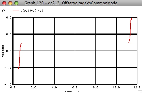
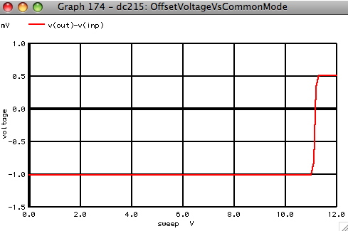
Each input stage is going to have its own unique input
offset voltage. There will be an offset shift whenever
one of the stages turns off when the inputs approach
one of the rails. For instance the plot above shows
what happens when the PNPs have -1mV of offset and the
NPNs have +0.5mV. At the bottom rail there is only the
PNP offset and only the NPN offset at the top rail.
A more preferred arrangement
in offset shift is shown
below. The customers want pretty much a LM324 input stage
which has the ability to shift from a PNP input to a
NPN input at the top rail.
A "tail current"
steering circuit is needed like what
is shown below. If PNP transistor QPS
is a lateral PNP,
then QPS can be
biased up to do all the current steering
on its own. Normal the emitter base of QPS is reversed
biased and off. All tail current will flow in the
PNP input transistors until the two inputs approach
the top rail. Before the input PNPs turn off, transistor
QPS will steal all the tail current and mirror it
to NPN inputs.
_______
^
VCC
_____________________________| |
/_\
|
____________________| |
_______|____ ^
VCC
|
| ^
VCC | |
| |
/_\
|
|
/_\ | |
-> <- |_/\
/\ /\_|
|_/\ /\ /\_|
| |
`|_|' \/
\/ |
| \/
\/
| |
_
'|||`_
_|
|_
| |
|____|
|
__|' VNPN
`|___
| |
/
| |
|`->
<-'|
|
| |
\
|
| |_________|
|
| | Comp Cap
/
|__________/|\__
|
|
|DUAL |
\ <-
___ | \
|
| ___
| | ___||_______
|____|' QPS
|INP|___| \
|
|______|INN| |INPUT | |
|| |
_|_
|`_ |___| |
\
|
| |___|
| |
| |
/ _
\ |
_|_ | \
|
| |
|TURN |
| |
\/ \/ ____|
/VIN\ | |
|
| |
| |___|_|\ _ _
| ___
/\_/\
| \___/
|
_/|\_|
| | |AROUND
| | \/ \/ \_|_|OUT|
\___/
| _|_
| /
|
| |
| | ___| /\_/\_/
|___|
_|_
| ///
| /
|
| |
| | |
|/ |
/// |
___________/|\_/
_|_______
| |
| |
|
|
|
|
|
|
|
| |
| |
_|_
|
|
|
|
<-
->
| |
| | \ /
VREF |
____|
|
|_|' VPNP
`|_| |
| |
V
|
|_ |
_|
|`_
_ '|
| |
|
|
`|_|_|' _/\ /\
/\_|
|_/\ /\ /\_ |
|
|
|
<-'|
|`-> _|_ \/ \/
|
| \/ \/ _|_ |
|
|
|
_|_
_|_ \\\
|
| ///
| |
|
|
///
///
|
|______________/|\_|
|
|
|__________________________/|\_|
|
|
|
|_______|
|
|_____________________________|
The only problem to the
circuit above is that QPS needs to
be a lateral because it's emitter base junction will be reversed
biased by almost the full supply voltage when both inputs are
down close to the bottom rail. This process has vertical PNPs
which have at least ten times more beta and are a thousand times
faster. It is desirable to have the current steering happen as
fast as possible. A method was found
to do the steering using
vertical PNPs.
The LM324 uses lateral and substrate PNPs as inputs and only
needs to be able to work down to the lower rail. Each input
of the LM324 can be connected to either rail with out damaging
input transistors. But the LM6142 requires the use of both
vertical NPNs and vertical PNPs. Because of the Rail to Rail
input requirement and low supply voltage requirement, the input
stage needs to be hooked up pretty much as is shown above.
But there is now a need for
input clamp diodes.
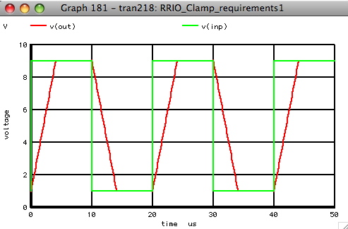
Using a RRIO Op Amp in a voltage follower application shows
that
the output will slew to follow the input and will apply
a large amount of differential voltage across the inputs. The
slew rate is maximum when the full tail current is being applied
to the compensation capacitor. The output voltage as shown below
will ramp up or down to try and follow the input voltage.
The input transistors need
to have differential input voltage
clamped during the slew period. This is normally done
using two diodes and a current
limiting resistor.
_______
________________________| |
|
_____
| |
| |_ |
______________| |
_| `|_|
|_
| |
__|'____<-'| |___`|___
| |
| |`->
<-'| |
| |
| |_________|
|
| | COMP CAP
| _|_ ^
VCC | |DUAL |
___
| / _ \ INPN /_\
|
| | ___||_______
|INP|___/\ /\ /\_| \/ \/ |
_|_ | ___ |INPUT
| | || |
|___| \/ \/
| /\_/\ V ^ / _ \ |_|INN|
| |
| |
_|__
| \___/ | \/ \/ | |___|
|TURN |
| |
/_
\
| _|_
/\_/\ | |
| |___|_|\ _ _
| ___
// \
\
| /// IPNP \___/ |
| |AROUND | | \/ \/ \_|_|OUT|
\
\_//
|
_________| | |
| | ___| /\_/\_/
|___|
\____/
|
|
| | |
| | |
|/ |
|
|
<-
-> | |
| |
|
|
_|_
|_|'_____ _____`|_| |
QN| |
_|_
|
///
|`_ -> | _
'| |
| | \ /
VREF |
| `|_|
| |
| |
V
|
| _ '| |
|________/|\__|
|
|
|
|_____|
| |
|
|
|____________________/|\__|
|
|
|
|_______|
|
|______________________________|
But clamp diodes are nothing
more than transistors which have
their collector bases shorted together. What would happen
if the collector where instead fed into
the signal path?
_______
________________________| |
|
_______
| |
| |_
|______________| |
_| `|__
|_
| |
__|'____<-'| |___`|___
| |
| |`->
<-'| |
| |
| |_________|
|
| | Comp Cap
| _|_ ^
VCC | |DUAL |
___
| / _ \
/_\ |
| | ___||_______
|INP|___/\ /\ /\_| \/
\/ _|_ |
___ |INPUT | |
|| |
|___| \/ \/
| /\_/\ / _ \
|_|INN| | |
| |
_|__
| \___/ \/ \/ |
|___| |TURN |
| |
/_
\
| _|_
/\_/\ | |
| |___|_|\ _ _
| ___
// \
\
| ///
\___/ | | |AROUND
| | \/ \/ \_|_|OUT|
\
\_//
|
_________| | |
| | ___| /\_/\_/
|___|
\____/
|
|
| | |
| | |
|/ |
|
|
<-
-> | |
| |
|
|
_|_
|_|'_____ _____`|_| |
QN| |
_|_
|
///
|`_ -> | _
'| |
| | \ /
VREF |
| `|_|
| |
| |
V
|
| _ '|
|________/|\__|
|
|
| |_______|
| |
|
|
|____________________/|\__|
|
|
|
|_______|
|
|______________________________|
The result is shown below.
While the input transistor are
being clamped, the current in the now clamp transistors
are being expressed across the compensation capacitor
to greatly increase the slew rate.
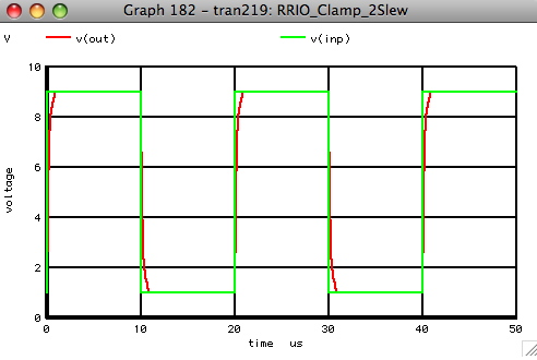
The clamp enhanced
slew rate has only an effect when the
clamps are on. Once the output gets close enough to the
inputs to come out of clamping, the settling continues
as normal.
The next stage of the LM6142 is the "dual input turnaround"
which is shown below. This stage needs to be able to
receive differential current from either input stage and
put out a bi-directional output current.
The input transistors are outputting their collectors to
resistors which drive emitter nodes in this turn around
stage. Driving current into emitters (common base drive)
is the fastest way to drive a transistor. Each collector
of the input stage is driving the emitters both a diode
and a transistor in a cross coupled fashion. The diode
cross couple signal to opposite transistors. One of the
collectors of the transistor is at the output node and
the other collector couples signal to mirror off the
opposite rail to provide the second output collector.
^ VCC
RN2 /_\ RN1
_/\ /\ /\_|_/\ /\ /\_
| \/ \/ \/
\/ |
|___________________ |
|
| |
_______________________/|\_________________/|\___|
|
________________|
|
| |
|
|
-> ->QP4 QP5 <- <-
_|
|_
QP3`|___`|_ _|'___|' QP6
__|'QN1
QN2`|___
_ '| _'| | ||`_ |`_
| |`->
<-'|
|
| |____| |___| |
| |_______|
|
| |
| |
|INPN_|_
^ VCC
|
|____/|\_____/|\_ |
CCOMP
___ | / _
\ /_\
|
_|_ | |
| ___||_______
|INP|___| \/ \/
_|_ |
___ / _
\ | |
| | || |
|___| | /\_/\ / _
\ |_|INN|
\/ \/Ibias|
| |
| |
_|__ | \___/ \/
\/ | |___|
/\_/\ | |
|
| |
/_ \ | _|_
/\_/\ |
|
\___/ | |
|____|_|\ _ _ | ___
// \ \ | ///
\___/ | |
| |
| | | \/ \/
\_|_|OUT|
\ \_// |
_______|IPNP
| |
_______/|\______| | | ___|
/\_/\_/ |___|
\____/ | |
| | |
| __|_
____| | |
|/ |
| |
<-
-> | |
|_ |_ | |
_| _| |
BOTA |
_|_
|_|'QP1 QP2`|_| |
QN3 `|____`|_| |_|'____|'QN6
_|_
|
///
|`_ _
'| | <-'| <-'|
|`-> |`-> \ /
VREF |
|
|________/|\__| | QN4
QN5 | |
V
|
|
| |
|
|
|
|
|__________________/|\_/|\____|____________/|\____|
|
| |___________________| |
|
|
|
|
|
| |_/\ /\ /\___/\ /\
/\_|
|
| RP2\/ \/ _|_ \/
\/
|
|
///
RP1
|
|_________________________________________________|
What is not obvious is that
this turn around stage is self
biasing. Current source Ibias can be made much smaller than
either INPN or IPNP and all the transistors can
increase in
current such that the available output current to the
compensation capacitor CCOMP is still +/- INPN
or IPNP.
In other words this dual input turn around
stage is AB Biased.
That means it can conduct a much higher level of signal current
relative to its DC current. This has both input offset and
input noise advantages.
A typical 1mV mismatch in bipolar transistors corresponds to
a 4% area ratio mismatch or current mismatch. When Ibias
is much lower than INPN
or IPNP, that is 4% mismatch of a much
smaller current.
The best way to
see this effect is to run a simulation
which
one by one introduces a single 1mV misbmatch and printout the
impact it has on input offset.
MissMatch
Device Input_Offset_mV
0%
QP1 -7.71252E-07
4%
QP1 -1.0134
4%
QP2 +1.0134
4%
QP3 +0.262465
4%
QP4 -0.26256
4%
QN1 +0.00101179
4%
QN2 -0.00101337
4%
QN3 -0.2625
4%
QN4 +0.262525
1%
RN1 +0.102932
1%
RN2 -0.102494
1%
RP1 -0.359263
1%
RP2 +0.35926
The actual standard
deviations of mismatch typically are well
under 1mV or 1% for resistors. But these values are just being
used for convenience. It is standard practice that the input
transistors by themselves should dominate both the Op Amps
offset and noise. Both noise and offset add with the power.
So adding 1mV standard deviation mismatch to a 1/3mV standard
deviation mismatch is..
sqrt( 1^2 + (1/3)^2) = sqrt(10/9) = 1.054
Any offset standard deviation mismatch or noise rms value
that
is three time larger will domination the power sum. As desired,
the input transistors dominate
both noise and offset.
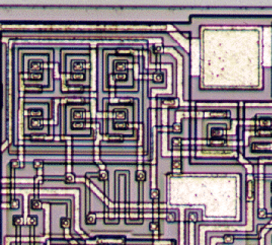
The LM6142 process is very
close to the old standard bipolar
process. The minimum geometry transistors are not much
smaller than pads in area. Stray capacitance is talked more
in terms of picoFarads. For the
LM6142, the stray emitter
base capacitance define the whole design. The emitter
base junction has an impedance of 26KOhms at 1uA. If
stray emitter base capacitance is 0.3pF, this put the
3dB point at 20MHz.
___
|(C)| NPN
SPICE
MODEL
|___|
|
/ RC 200ohms VAF 200
\
/
1pF
________________________|_____________________
| |
| |
| |
_|_ _|_Cjs
| |.3pF
| | |Ir/BR |Irn / _
\ ___
| |
| / _|_
_|_ \/ \/ |gnd!
_|_Cjcx _|_Cjc _|_Cdc
\ ^ ^
/\_/\ _|_
___
___ ___ /
/_\ /_\ \___/ \sub/
___ | Rbb'| |
gmin \ | |
Ic | \ /
|(B)|_|_/\
__|______|______|____|______| |
| V
|___| \/
| |
| _|_ _|_ | V
300ohms _|_Cje _|_Cde
\ \ / \ / |
BF 160 ___
___ / _v_
_v_ |
IE<2.5mA |.3pF | gmin
\ |If/Bf |Ifn |
|______|______|____|______|______|
|
TF .18us
/ RE 5ohms
\
/
_|_
|(E)|
|___|
In a current starved design,
the stay capacitances and
currents through diodes define the speed of transistors
which in turn ultimately defines stability for a given
bandwidth. Emitter current needs to be increased to close
to the beta roll off in order to see the effects of TF.
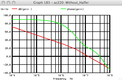
Just
adding emitter base
capacitance to the turn around
simulation and nothing else reveals that the Op Amp would
have about 20 degrees of phase margin running in this current
starved mode.
The LM6142 is a
very current starved design in
that greater than 10MHz bandwidth is needed running under
1mA of supply current. Every transistor is running at
minimum current.
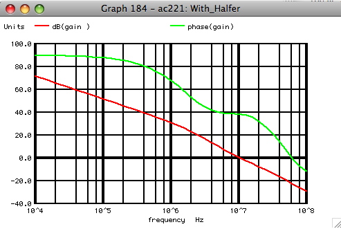
Even so, there are some old
design tricks that can be
applied. By adding two capacitors to the turn around
stage as shown above, it is possible to actually
reduce high frequency gain and high frequency phase
delay at the same time. This
is a little counter
intuitive since
decreasing high frequency gain
normally increases high frequency phase delay.
The following is what is going on.
^ VCC
/_\
_/\ /\ /\_|_/\ /\ /\_
| \/ \/ \/
\/ |
|___________________ |
|
| |
_______________________/|\_________________/|\___|
|
________________|
|
| |
|
|
-> -> C2 <-
<-
_|
|_
`|___`|__||__|'__|'
__|'
`|___
_ '| _'| ||| ||`_
|`_
|
|`-> VNPN <-'|
|
| |____| |___| |
| |_______|
|
| |
| |
|INPN_|_ ^
|
|____/|\______/|\_ |
___ | / _
\ /_\
|
_|_ | |
| ___||_______
|INP|___| \/ \/
_|_ |
___ / _
\ | |
| | || |
|___| | /\_/\ / _
\ |_|INN|
\/ \/IABB | | |
| |
_|__ | \___/ \/
\/ | |___|
/\_/\ | |
|
| |
/_ \ |
_|_ /\_/\ |
|
\___/ | |
|____|_|\ _ _ | ___
// \ \ | ///
\___/ |
|
| | |
|
| \/ \/ \_|_|OUT|
\ \_// |
_______|IPNP | | _______/|\_______|
| |
___| /\_/\_/ |___|
\____/ |
| |
| | |
__|_ ____| | |
|/ |
| |
<-
-> | | |_
|_ |_||_|
_| _|
|
|
_|_
|_|'
`|_| | `|___`|_| || |_|'____|'QN6
_|_
|
///
|`_ _
'| | <-'| <-'| C1 |`-> |`-> \ /
VREF |
|
|________/|\__|
|
| |
V
|
|
| |
|
| |
|
|__________________/|\_/|\___|_____________/|\____|
|
| |___________________|
|
|
|
|
|
|
| |_/\ /\ /\___/\ /\
/\_|
|
| \/ \/ _|_
\/
\/
|
|
///
|
|_________________________________________________|
The input transistors
collectors are driving the transistors
in the turn around stage in a common
base format already.
This can be further improved by adding capacitor C1 to the base
of QN6. But by also adding
capacitor C2, the high frequency
signal path through all transistors except QN6 is killed.
Since only one input transistor's collector is common base driving
QN6, the current gain is one half of the DC value. But now the
turn around stage consists of only the fastest current path. So gain
is reduced, but so is phase delay. This method is sometimes called
"shortening the signal path".
At lower frequencies the LM6142
needs more transistors in the signal path for Rail to Rail
input operation and low input offset voltage and supply and
common mode rejection. But there is no reason why all these
current starved transistors can't be by-passed at higher
frequencies for the sake of stability.
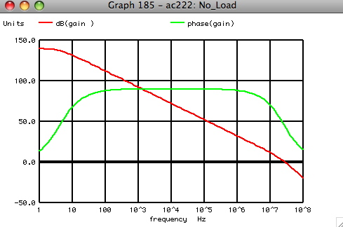
A Rail to Rail Input/Output
Op Amps are really just two
transconductance amplifiers connected in series with
a compensation capacitor across the output transconductance
amplifier. This adds a special current gain requirement to the
transconductance amplifier. Without a output load resistor,
the open loop gain of the Op will be set by the early
voltages of the transistors which can be quite high.
^ VCC
/_\
_/\ /\ /\_|_/\ /\ /\_
| \/ \/ \/
\/ |
|___________________ |
|
| |
______________________/|\_________________/|\___|
|
________________|
|
| |
|
|
->
-> <-
<-
_|
|_
`|___`|_ _|'___|'
__|'
`|___
_ '| _'| | ||`_ |`_
|
|`-> <-'|
|
| |____| |___|
| ___||_______
| |______|
|
| |
| | |
|| |
|INPN_|_ ^
|
|____/|\_____/|\_ |
| |
___ | / _
\ /_\
|
_|_ | |
|
| |
|INP|___| \/ \/
_|_ |
___ / _
\ | | |____|_|\ _ _
| ___
|___| | /\_/\ / _
\ |_|INN|
\/ \/ | |
| | \/ \/ \_|_|OUT|
_|__ | \___/ \/
\/ | |___|
/\_/\ | |
| ___|
/\_/\_/ |___|
/_ \ | _|_
/\_/\ |
|
\___/ | |
| _|_
|/ |
// \ \ | ///
\___/ |
|
| | |
| \
/
OUTPUT
STAGE |
\ \_// |
______|IPNP | |
_______/|\______| | | V
|
\____/ |
| |
| | |
__|_ ____|
| VREF
|
| |
<- ->
| | |_ |_
| | _| _|
|
_|_
|_|'
`|_| | `|____`|_|
|_|'____|'
|
///
|`_ _
'| | <-'| <-'|
|`-> |`->
|
|
|________/|\__|
|
| |
|
|
| |
|
|
|
|
|_________________/|\_/|\____|____________/|\____|
|
| |___________________|
|
|
|
|
|
|
| |_/\ /\ /\___/\ /\
/\_|
|
| \/ \/ _|_
\/
\/
|
|
///
|
|_________________________________________________|
But when an output load is
applied, a change in output current
in the out transconductance amplifier can result in a
change in it's input bias current. The input transconductance
amplifier will have to develop an input offset to counter this
extra needed input bias current which results in the lowering
of open loop gain with an applied output load.
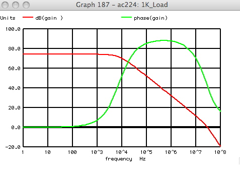
In the LM6142, the current
gain is set by the beta of a NPN
darlington and a vertical PNP. There is a 600 Ohm customer
requirement for the LM1642. A free way was
found to address
this loading issue.
^ VCC
/_\
_/\ /\ /\_|_/\ /\ /\_
| \/ \/ \/
\/ |
|___________________ |
|
| |
______________________/|\_________________/|\___|
|
________________|
|
| |
|
|
->
-> <-
<-
_|
|_
`|___`|_ _|'___|'
__|'
`|___
_ '| _'| | ||`_ |`_
|
|`-> <-'|
|
| |____| |___|
| ___||_______
| |______|
|
| |
| | |
|| |
|INPN_|_ ^
|
|____/|\_____/|\_ |
| |
___ | / _
\ /_\
|
_|_ | |
|
| |
|INP|___| \/ \/
_|_ |
___ / _
\ | | |____|_|\ _ _
| ___
|___| | /\_/\ / _
\ |_|INN|
\/ \/ | |
| | \/ \/ \_|_|OUT|
_|__ | \___/ \/
\/ | |___|
/\_/\ | |
| ___|
/\_/\_/ |___|
/_ \ | _|_
/\_/\ |
|
\___/ | |
| |
|/ |
// \ \ | ///
\___/ |
|
| | |
| | OUTPUT
STAGE |
\ \_// |
______|IPNP | |
_______/|\______| | | |
|
\____/ |
| |
| | |
__|_ ____|
| |
|
| |
<- ->
| | |_ |_
| | _| _| ->
|
_|_
|_|'
`|_| | `|____`|_|
|_|'____|' `|_
|
///
|`_ _
'| | <-'| <-'| |
|`-> |`-> _ '|_|_
|
|
|________/|\__| | |_______/|\___/|\___| \
/ |
|
| |
|
|
|
V |
|_________________/|\_/|\____|____________/|\____|
VREF |
| |___________________|
|
|
|
|
|
|
| |_/\ /\ /\___/\ /\
/\_|
|
| \/ \/ _|_
\/
\/
|
|
///
|
|_________________________________________________|
While it is not possible to
know the product of three betas,
it was possible to effectively measure the input bias current
loading. It just so happens that the output transconductance
amplifier needed a PNP to buffer
its VREF voltage. Normally
this would be done with a PNP emitter follower. But when
the loading at the output stage creates a change in input
bias current, both inputs of a symmetrical transconductance
amplifier tend to see a change in equal but opposite magnitudes.
An this PNP emitter follower is seeing the other input.
Instead of connecting the collector of the PNP to ground, is
there somewhere in the dual
input turn around where this changing
input bias current can be applied to effectively cancel out the
output loading effects? The circuit above shows somewhat how
this was done. The technique is referred to as "Beta Balancing".
The first two stages of the
LM6142 have already defined some of
some requirements for the output transconductance stage.
The requirements for the
output stage are..
1) High current gain
2) Low supply voltage
3) Low supply current
4) Stability with 100pF load
5) Current limit
6) Swing close to both rails
7) No shoot through current
_______________________________________________________________________
|
|
|
________________||_________________________________ |
|
|
|| CCOMP
|
| |
|
|__________|\ _ _
|
| |
|
| - | \/ \/
\______|
VREF
| |
|
| ___|
/\_/\_/
_____________________ | |
|
| |+
|/
B_PNPOUT|
| | |
|
| |__________________|
VP5C
R7 |
| |
_|_
|
__________/\ /\____| | |
|INN|_
|
VPNP ^
VCC
|
\/ | | | |
|___|
|
| ___
/_\
| _/\ /\_| |
| _|_
| VIIN |IP _|_ |
_______|________ |
| \/ R6| | |_|OUT|
|_|\ _ _
| / _ \ | |
| | |
|___ | | | |___|
___ | \/ \/ \__| \/ \/ |
-> <- <-
|
| _| | |
|INP|___| /\_/\_/ | /\_/\ | QP4 `|_|'QP3|'QP5 |
__/\ /\_|_|'QN5 | |
|___|
|/ | \___/
| _ '|||`_ |`_ | _|_
\/ |`-> | |
_|_
| _|_ |__|____| |
| | /// R5 VREF2 _|_ | |
/VIN\ B_RRIN |
///
|
|__|
/// | |
\___/
|
______________|______________
| |
_|_
| |
VPNPE
| | |
///
|
<-
-> | |
|_|'
QP1
QP2 `|_______| |
|`_
_ '| |
VCC ^
|
| ^ VCC |
/_\ |
| /_\ |
|_ |
R2
R3 | _| 5X |
QN1 `|_|_/\ /\ /\_________/\ /\ /\_|___|'
QN3 |
<-'| \/ \/
| \/
\/ |`->
_|
|____________
_|
R4 |___|' QN4
|_|'
QN2
| |`->
__/\ /\___|
|`->
__/\ /\____| _|_
_|_ \/ R1
_|_
_|_ \/ VN4B ///
/// VN2B
/// ///
For the LM6142, the output
transconductance stage consists of
two transconductance stages. The NPN stage is shown above and it
drives the NPNs which pull the output to the bottom rail.
The PNP stage is an exact mirror of the NPN stage and its output
PNP pulls the output to the top rail. This stage is for
now being represented by a transconductance block.
It should be noted in this design that only the output
voltage node is moving more than a couple of hundred millivolts
while this Op Amp is operating. The base of QN3 is designed
to move only this amount to supply the output current. The base
of QN1 and VREF and all
other voltage nodes are meant to stand still.
The amplifier is in sense just
steering currents around between
transistors. Only the output is meant to slew any voltage. So it
is a one slew node Op Amp design.
Transistors QP3, QP2, QN3, and
QN4 only require a supply voltage
of 2 diodes and two sats to operate, just like the input stage.
Transistors QP1, QN3, and QN4
define the
input to output current
gain.
While VREF wants to
be at half supply at low voltage, it wants to
be at a higher at a more stable level for 5Vs and above. Resistors
R5, R6, and R7 and transistors QP5
and QN5 are designed to product
the curve below.
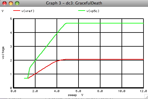
The LM1642 follow somewhat
the curve above. There was a need for
something called "graceful
death" at the time. It was important
that an Op Amp should not go crazy as the supply voltage slowly
dropped. The customers wanted an Op Amp to be functional and
slowly degrade in performance as the supply voltage drops.
The LM6142 was originally designed for the 5V and 12V market.
So "graceful death"
start well below 5V. But it was found
that the part still did well at 2.4V and 24V, so these limits
were added to the spec.
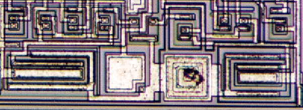
The current starved
requirement forces the output transistors
to be as small as possible. Somewhere between one half
and one third of the whole LM6142's supply current
flow in just the two output transistors. The die photo
shows that while minimum geometry's may not much smaller
than a pad, the output transistors are not much larger.
The output transistors are at their close to their beta
rolloff limit. All transistors are running at as low as
current as possible. This means they all have excessive phase
delay.
___________________________________________________________________________
|
|
|
________________||___________________________ |
|
|
|| CCOMP
|
| |
|
|__________|\ _ _
|
| |
|
| - | \/ \/
\______|
| |
|
| ___|
/\_/\_/
| |
|
| |+
|/ B_PNPOUT
^
| |
|
|
|________________
/_\ |
|
_|_
|
|_______|
| |
|INN|_
|
^ VCC
|VREF
| |
|___|
|
| ___
/_\
|
| _|_
|
| _|_ | _______|___
|
|_|OUT|
|_|\ _
_
| / _ \ | |
|
|
| |___|
___ | \/ \/ \____/\ /\__| \/
\/ | -> <-
|
|
|INP|___| /\_/\_/ | \/
| /\_/\ | `|_|'
|
|
|___| |/ | RBYP |
\___/ | _
'|||`_
|
|
_|_
|
|
_|_ |__|____| |
|
|
/VIN\
|
|
///
| |___________ |
\___/
|
|
______________|________
| |
_|_
|
|
|
| | |
///
|
|
<-
-> | |
|
|_|'
`|_| |
|
|`_
_ '| |
|
|
CBYP
|
|
|______________/|\_________||_____
|
|
|
|| |
|
|
VCC ^
|
|
| ^
VCC |
/_\
|
|_______|
/_\ |
|_
|
| _| 5X |
`|_|_/\ /\ /\___/\ /\ /\_|___|'
QN3 |
<-'| \/ \/ |
\/ \/
|`-> _|
|____________
_|
|___|' QN4
|_|'
| |`->
__/\ /\___| |`->
__/\ /\____| _|_
_|_ \/
_|_ _|_
\/ ///
///
/// ///
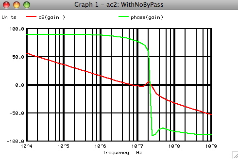
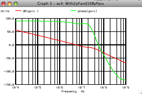
The same "shorten signal path" needs
to be applied to the
output stage. The gain phase
plot below shows that the circuit
above is just getting ready to oscillate with due to stray C
in the simulation. In this case RBYP is set to one Ohms and
CBYP is set to 0.2pF.
Changing CBYP to 2pF makes a big difference in stability.
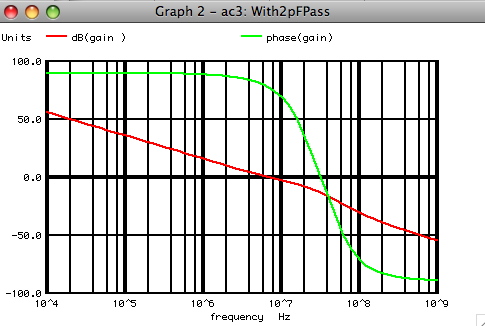
Changing RBYP to 1kOhm extends the phase margin
to higher frequencies. This was done to allow
stability with capacitive loads.
The actual gain phase plots
of the LM6142 show
the effects of a 100pF load.
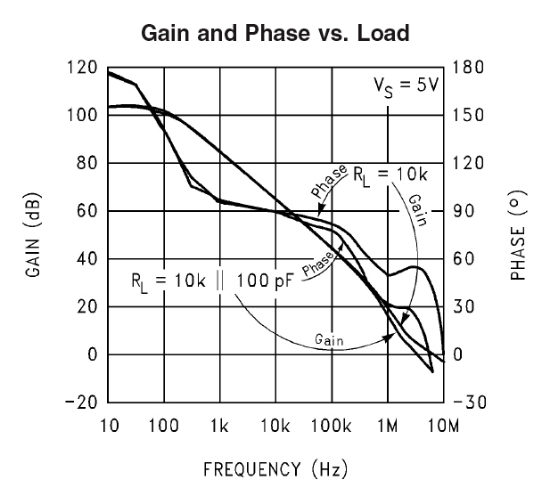
The Gain Band Width Produce for
the LM1642 is 17MHz.
But the unity gain cross
is at least 5Mhz or
lower.
Having a difference between GBWP
and unity gain
depends on the application.
Because the Rail to Rail input requirements define the
input stage architecture, a differential input signal
greater than +/-50mV will distort. Any one who wants
to operate an Op Amp at unity gain needs both the input
and output signal levels to be non distorted and above
the noise. The LM6142 was designed to provide lots of gain
at the audio bandwidth with low supply current. The only
high frequency requirement was stability.
______________________________________________________________________
|
|
|
________________||________________________________ |
|
|
|| CCOMP
|
| |
|
|__________|\ _ _
|
| |
|
| - | \/ \/
\______|
^
| |
|
| ___|
/\_/\_/
/_\
| |
|
| |+
|/ B_PNPOUT
|
| |
|
|
|________________
|
| |
_|_
|
|_______|
| |
|INN|_
|
^ VCC
|VREF
| |
|___|
|
| ___
/_\
|
| _|_
| |IP
_|_ | _______|___ | ^
VCC
|_|OUT|
|_|\ _ _
| / _ \ | |
| |
/_\
| |___|
___ | \/ \/ \__| \/ \/ |
-> <- |
|
RST
|
|INP|___| /\_/\_/ | /\_/\ |
`|_|' | |__/\ /\_
VST |
|___|
|/ | \___/
| _ '|||`_
| \/
| |
_|_
| _|_ |__|____| |
|
| |
/VIN\
|
///
| |___________
| |
\___/
|
______________|________ |
| R8 |
_|_
|
|
| | | _/\ /\_|
///
|
<-
-> | | | \/ |
|_|'
`|_| | | |
|`_
_ '| | |_ QN5
|
VCC ^
|
| _| `|_ |
/_\
|
| | <-'| | |
|_
|
| QN3 _|
| __| |
`|_|_/\ /\ /\___/\ /\ /\_|___|'_____|
| |
<-'| \/ \/ |
\/ \/
|`-> | _|
|____________
_|
|_____|__|' QN4
|_|'
| |`->
__/\ /\___| |`->
__/\ /\____| 5X _|_
_|_ \/
_|_ _|_
\/
///
///
/// ///
There are extra customer
expectations which go into
designing an Op Amp. When an output transistor
in a RRIO Op Amp hits a rail, a transistor such
as QN3 will try and drive
a lot of current into
the base of the output transistor.
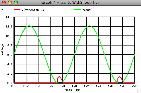
This creates two problems.
First there will be a
large increase in supply current whenever an output
transistor saturates. This was called "shoot through".
Second a large amount of base current will be dumped
into the output transistor causing a delay in its
being able to turn off. This was called "hang
on".
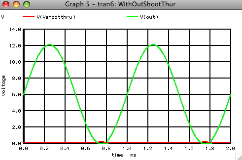
What was needed was a
saturation current limit circuit.
This just involves using upside down transistor together
with an adjustment resistor.
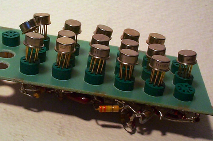
The LM6142 design perhaps
represents the limit of bread
boarding.
It was possible to somewhat breadboard this current starved
design. A rule of thumb had been that the bread board adds
about 2pf on each lead of a transistor. Where as the stray
capacitors in all the transistors were under this level,
the breadboard needed to be scaled in terms of same current,
10X capacitance relates to about one tenth the speed.
The VIP2 process shown
below is pretty close to the old standard
bipolar process. In this process, stray capacitance's are in
picoFarads and there is a struggle to put in as few of transistors
as possible.

For comparison, a 5V BiCMOS
layout is shown below
with the pads scaled to the same size. Now stray capacitances
are in femtoFarads and a single NPN transistor is smaller
what an emitter contact used to be.
The small transistors can put out an amazing amount of
current
for their size. The NPN models for a minimum geometry in the
die photo above is show below. Process development has been
resulting in amplifiers with much higher speed at much lower
supply current. The same relationship of supply current versus
stray capacitance defines speed still applies. But now things
are in terms of femtoFarads, picoseconds, and microAmps.
And processing has moved on to silicon/germanium transistors
and full oxide isolation.
___
|(C)| NPN
SPICE
MODEL
|___|
|
/ RC 110ohms VAF 200
\
/
4fF
________________________|_____________________
| |
| |
| |
_|_ _|_Cjs
| |12fF
| | |Ir/BR |Irn / _
\ ___
| |
| / _|_
_|_ \/ \/ |gnd!
_|_Cjcx _|_Cjc _|_Cdc
\ ^ ^
/\_/\ _|_
___
___ ___ /
/_\ /_\ \___/ \sub/
___ | Rbb'| |
gmin \ | |
Ic | \ /
|(B)|_|_/\
__|______|______|____|______| |
| V
|___| \/
| |
| _|_ _|_ | V
600ohms _|_Cje _|_Cde
\ \ / \ / |
BF 116 ___
___ / _v_
_v_ |
IE<0.5mA |20fF | gmin
\ |If/Bf |Ifn |
|______|______|____|______|______|
|
TF 8ps
/ RE 45ohms
\
/
_|_
|(E)|
|___|


